Simulated application of loads
Even with a rectilinear building it is difficult to asses the loads that may be imposed due to the variables of weather and in particular wind, which can exhibit unpredictable eddies and turbulence. When the force calculation is made more difficult due to the three dimensional form of a membrane there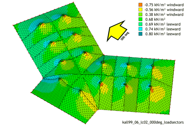 are only three ways to assess the potential forces.
One is to apply an overall pressure co-efficient (uniform load) which makes allowance for most conditions. While factors of safety are a vital part of engineering, over engineering can be detrimental to a project and not just on the grounds of cost. We use software applications which break down the surface of the membrane, sector by sector and apply a simulated load determined by direction of force and angle of approach. This provides a more accurate method of determining potential force. This of course also makes it easier to comply with building code in the chosen locale. Portable structures rarely have snow load applied to them unless used regularly in such climates. Rain can be an issue if the membrane is being rolled out on the floor and it fills with water. Before long there can be the equivalent of two ro three cars weight laying in the membrane. It can take hours to remove the water from such a situation.
Wind loads are varied and factored by amounts determined by size and shape of structure, locational parameters, (open countryside will usually have lower wind speeds than sheltered inner city sites), and duration of installation. Surface pressures increase in proportion to the square of the wind speed. Therefore the pressures upon the surface of the structure are much greater than a small increase in the stated wind speed would first suggest.
Simulated pressures from two different angles
Surface pressures should be calculated for walled structures with the walls attached. Dominant openings such as sections of wall left open are not 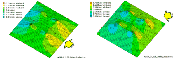 normally allowed for. Smaller openings such as large doors are catered for by allowances in the initial calculations. A major consideration can be uplift. Uplift is often the dominant part of wind loading considerations, as is the effect of suction. The illustrations show the representative mesh with simulated wind loads broken down, polygon by polygon. Once the potential membrane loading estimates or pressure coefficients (CP) are confirmed, then attention must be made to the supports, lifting gear, ground anchors and other factors such as stiffening members such as webbing belts or spars.